A schematic diagram is a symbolic drawing that shows how electrical parts are connected in a circuit. Instead of showing components the way they physically look on a table or breadboard, it uses standard symbols and lines to show the circuit logic clearly.
Last updated: June 18, 2026
Why Beginners Need This Explanation
Many students can copy a physical build from a photo but still freeze when they see a schematic. That is normal. A photo shows where things look like they are placed. A schematic shows how the circuit is connected. Once students understand that difference, troubleshooting becomes much easier.
SparkFun’s schematic guide describes schematics as the map used to design, build, and troubleshoot circuits. That “map” idea is one of the best ways to introduce them in class.
What a Schematic Diagram Shows
A schematic does not try to look realistic. A resistor may appear as a zig-zag or rectangle. A battery may appear as a pair of long and short lines. An LED may appear as a diode symbol with arrows. The goal is not visual realism. The goal is connection clarity.
OpenStax Physics explains that circuit diagrams use lines and symbols to represent elements in a circuit. That sentence is a solid classroom definition because it keeps students focused on what matters: symbols for parts, lines for connections, and a path for current.
Photo vs Wiring Diagram vs Schematic
| Format | What it is best for | What it hides or makes harder |
|---|---|---|
| Photo | Seeing real parts and placement | Electrical logic can be hard to trace |
| Wiring diagram | Following exact placement or color-coded connections | Can become cluttered as circuits grow |
| Schematic | Understanding how the circuit works | Does not show physical layout directly |
A Simple Schematic Example
Imagine a battery, a switch, a resistor, and an LED in one loop. On a breadboard, those parts may be spread out across several rows. On a schematic, they may appear in a neat line. That does not mean they are physically next to each other. It means they are electrically connected in that order.
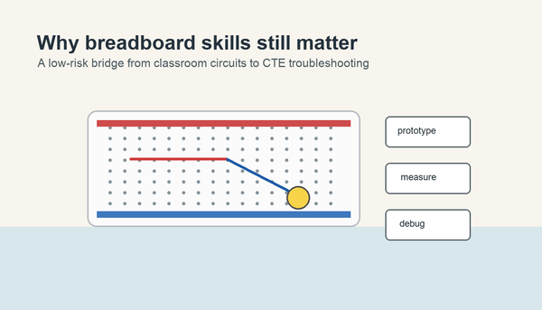
This is why students who are already comfortable with a solderless breadboard still need diagram-reading practice. Breadboards teach placement. Schematics teach circuit structure.
How to Read a Beginner Schematic
- Find the power source first.
- Identify the load, such as an LED, lamp, buzzer, or motor.
- Follow the lines between symbols and name each connection out loud.
- Look for switches, branches, and components that control current or voltage.
- Ask whether the path is complete, open, series, or parallel.
This routine helps students connect schematics back to ideas they may already know from open vs closed circuits and series vs parallel lessons.
Common Symbols Beginners Should Learn First
- Battery: the source that provides electrical push.
- Resistor: a component that limits current or shapes circuit behavior.
- Switch: opens or closes the circuit path.
- LED or diode: direction-sensitive component with polarity.
- Ground or common reference: a labeled return point used in many diagrams.
SparkFun’s guide is helpful here because it shows that the symbols are standardized enough to be readable across many beginner projects. Students do not need every symbol on day one. They need a small, reusable starter set.
Why Schematics Matter for Troubleshooting
When a circuit fails, a schematic gives students a clearer way to think. Instead of staring at a messy bundle of jumper wires, they can ask structured questions: Is the switch in series with the load? Does the LED polarity match the symbol? Is the resistor on the intended path? Is the branch open or bypassed?
This is one reason a schematic-reading lesson pairs well with build-and-test activities such as a continuity tester. Students can compare the symbolic path to the real build and then diagnose errors with more confidence.
Common Beginner Mistakes
- Thinking the left-to-right drawing shows exact physical placement.
- Ignoring labels and following only visual shape.
- Missing a branch because the student is looking at parts instead of connection lines.
- Confusing a wiring photo with a schematic and expecting them to match visually.
- Forgetting that a diode or LED symbol also communicates direction.
A Good Teacher Move: Translate Back and Forth
One of the best routines is to show a very small circuit in three forms: photo, breadboard layout, and schematic. Ask students what stays the same across all three versions. The answer is the electrical relationship, not the appearance. That is the moment many beginners start to “get” schematic reading.
Teachers building introductory electronics sequences for classrooms, homeschool groups, or CTE labs can support this skill with the broader resources at Mr Circuit for schools and educators.
Sources and Further Reading
- SparkFun Learn: How to Read a Schematic
- OpenStax Physics: 19.2 Series Circuits
- OpenStax Physics: 19.3 Parallel Circuits
FAQ
Is a schematic diagram the same as a picture of a circuit?
No. A schematic shows symbolic connections, while a picture shows the real physical appearance of parts and wires.
Why do schematics use symbols instead of realistic drawings?
Because symbols make it easier to show circuit logic clearly, especially when circuits become more complex.
Should beginners learn breadboards or schematics first?
Either order can work, but students learn faster when they are taught how the two views connect to each other.
What should students locate first on a schematic?
Start with the power source, then trace the load and the path between them.
How does reading a schematic help troubleshooting?
It helps students see intended connections, spot missing paths, and compare the planned circuit to the physical build.