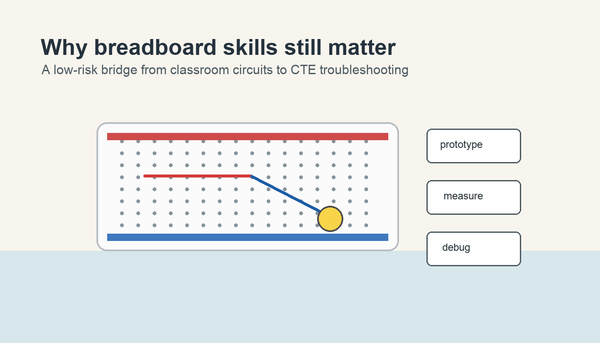
A solderless breadboard is a reusable plastic board with hidden metal clips that let students connect parts without soldering. The middle rows connect small groups of holes, the long side rails help distribute power and ground, and the center gap makes it easier to place chips and test simple circuits safely.
Last updated: June 6, 2026.
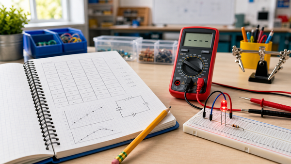
For many beginners, the breadboard is the moment electronics stops feeling abstract. Instead of only talking about current, voltage, and resistance, students can plug in an LED, resistor, and jumper wire and watch a circuit become visible. That is why a clear breadboard explanation matters before larger STEM or CTE builds.
Why teachers start with a solderless breadboard
SparkFun's breadboard tutorial explains that the point of a breadboard is to build circuits without soldering them permanently. Adafruit's beginner guide adds the practical detail teachers need: the board is reusable, organized, and built around hidden metal clips under the holes.
That makes a solderless breadboard ideal for classrooms. Students can make mistakes, move a wire, test again, and learn from the change instead of ruining the project. The Mr Circuit Lab 1 Basic Electronics STEM Kit uses that same no-solder approach because first builds should feel approachable, not fragile.
What each part of the breadboard does
| Section | What it does | Why students need it |
|---|---|---|
| Power rails | Carry power and ground along the side of the board | Give many places to connect the battery or supply |
| Terminal strips | Connect small groups of holes in rows | Let components share a connection without twisting wires together |
| Center gap | Separates the two halves of the board | Makes it easier to place integrated circuits and keep both sides distinct |
Adafruit describes most full-size breadboards as having three main areas: two long power rails and a larger center section made from repeated 5-hole strips. That single fact solves many beginner mistakes, because students usually assume every hole is connected to every other hole. It is not.
How the holes are connected
The easiest way to explain a breadboard is to say that it hides small connection groups under the surface. SparkFun and Adafruit both describe metal clips under the holes. When a part lead or jumper wire is inserted, that clip grips the metal and electrically connects it to the other holes in the same group.
On a typical board, the center working area is organized into short groups of five connected holes. The long side rails are different: they are designed to distribute power and ground over a longer distance. Students need to learn that the center rows are for component connections and the long rails are for power planning.
A simple first example
Place one LED so its two legs land on different connected rows. Then place a resistor so one end shares a row with the LED and the other end reaches a new row. Add jumper wires from the power rail to the resistor path and from the LED back to ground. That basic build teaches three things at once:
- Rows matter.
- Polarity matters.
- A breadboard is for testing a circuit layout before making anything permanent.
After that first build, the next useful articles are what voltage means, what current means, and what resistance means. The breadboard gives students a place to see those ideas, not just memorize them.
Common student mistakes on day one
1. Putting both legs of a part into the same connected row
If both legs of an LED or resistor land in the same connected strip, the part is not doing useful work in the circuit. It is effectively connected to itself on one node.
2. Treating the whole board like one big metal plate
Students often think every hole is connected. A quick teacher demo with a marker or printed diagram helps fix this before builds begin.
3. Ignoring the power rail labels
The rail colors are a guide, not decoration. If students mix up positive and ground, the circuit will not behave the way they predict.
4. Forgetting the center gap
The center gap is not wasted space. It is what allows chips and more complex parts to bridge both sides of the breadboard cleanly.
How to explain the center gap without jargon
Tell students the breadboard is really two working fields placed side by side. The center gap prevents the two sides from accidentally touching. That is especially useful when you begin working with integrated circuits, because the pins on one side of the chip need to remain separate from the pins on the other side.
If you are teaching with beginner kits, the gap also helps students organize their thinking. One side can become the input side, and the other can become the output side. That kind of visual structure matters for mixed-skill classrooms.
Why breadboards fit STEM and CTE so well
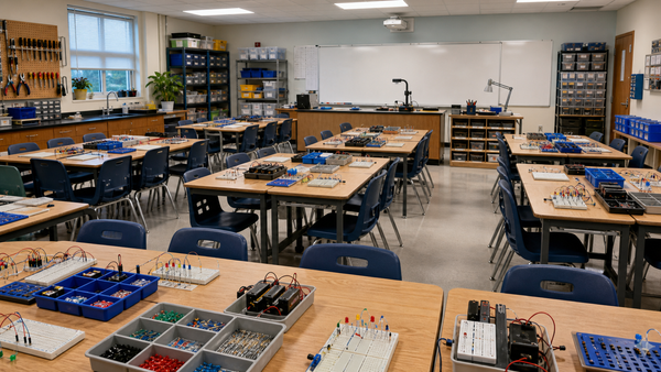
The For Schools and Educators page makes an important classroom point: students learn better when they can build, test, and rebuild without a high equipment barrier. A solderless breadboard supports that model because it lowers the setup cost of experimentation.
It also creates better lesson pacing. Teachers can spend less time on tool management and more time on prediction, troubleshooting, and reflection. That is a stronger first step toward real electronics than handing students a fixed, sealed project.
A quick classroom setup checklist
- Show the rails, rows, and center gap before handing out parts.
- Model one LED-and-resistor build on a document camera or projected diagram.
- Have students point to which holes are connected before they plug anything in.
- Use low-voltage power only.
- End by asking students to redraw the connection pattern in a notebook.
That last step matters. If students can sketch the connection logic after building, they are already moving toward reading schematics and troubleshooting with intention.
When to move from breadboards to the next concept
Once students understand how the board is organized, you can move quickly into useful beginner builds such as how a resistor works in a simple LED circuit. The hardware explanation should not take a week. It should take one lesson, then immediately support a real circuit.
For teachers building a fuller sequence, the MC1-SET classroom kit is the natural internal example because it scales the same breadboard logic to a full group environment.
Frequently Asked Questions
What makes a breadboard solderless?
It uses internal metal clips to connect parts temporarily, so students can build circuits without melting solder onto a board.
Are all five holes in a row connected?
In the center working area, many standard breadboards connect holes in short groups of five. The long side rails follow a different pattern for power distribution.
What is the center gap for on a breadboard?
The center gap separates the two sides of the board and makes it easier to place integrated circuits and keep both sides electrically distinct.
Why do beginners use breadboards first?
They let students test, move, and rebuild circuits quickly without making a permanent mistake.
Can students use a breadboard safely in class?
Yes, when the build stays low-voltage, teacher-guided, and properly current-limited for parts like LEDs.