Logic gates are simple digital circuits that follow clear input-output rules. They take binary inputs such as 0 and 1 and produce a binary output based on a pattern called a truth table. For beginners, AND, OR, and NOT are the best place to start because students can predict what should happen and then test that prediction in a real circuit.
Last updated: June 9, 2026
That matters because logic gates are often taught as symbols on a worksheet instead of as real physical behavior. Students do need the symbols, but they learn faster when they can connect the symbol, the truth table, and the circuit on the breadboard.
What a logic gate actually does
Khan Academy defines a logic gate as something that takes in values such as 0 or 1 and produces an output according to a truth table. Analog Devices describes logic gates in similar terms, focusing on Boolean functions such as NOT, AND, and OR. The beginner translation is simple: a logic gate checks a condition and then gives one predictable answer.
In a classroom, those inputs can be treated like switches that are either off or on. The output might be an LED that stays off or lights up. That makes logic feel much less abstract.
| Gate | What it asks | When the output becomes 1 |
|---|---|---|
| AND | Are both conditions true? | Only when both inputs are 1 |
| OR | Is at least one condition true? | When either input is 1 |
| NOT | What is the opposite of this input? | When the single input is 0 |
Why truth tables matter
A truth table is not just something to memorize. It is the fastest way to show students every possible input combination and the output that should follow. Once students see the full pattern, they can test whether a real circuit matches the expected behavior.
| Inputs | AND | OR |
|---|---|---|
| 0, 0 | 0 | 0 |
| 0, 1 | 0 | 1 |
| 1, 0 | 0 | 1 |
| 1, 1 | 1 | 1 |
| Input | NOT output |
|---|---|
| 0 | 1 |
| 1 | 0 |
These tables do important teaching work because they force students to think case by case. Instead of saying "I kind of get it," they must decide what should happen in every combination.
How to explain AND with a real circuit
The AND gate is the easiest place to start with two-input reasoning. Imagine two switches controlling one LED. If the rule is AND, the LED turns on only when both switches are on. If either switch is off, the output stays off.
That is a strong classroom example because students can speak the rule out loud: both conditions must be true. It also connects directly to robotics and automation. A system may act only when two conditions are satisfied at the same time.
How to explain OR with a real circuit
The OR gate changes only one idea. Instead of requiring both inputs, it needs at least one. If switch A is on, the LED can light. If switch B is on, the LED can light. If both are on, it still lights. Only the double-zero case keeps the output off.
This is useful for beginners because it models choice conditions clearly. The system reacts when one path or another becomes true.
How to explain NOT with a real circuit
NOT uses only one input and flips the state. All About Circuits is helpful here because it shows that inverter behavior can be produced by a real electronic circuit, not just a triangle symbol with a bubble. In student language, NOT means the output becomes the opposite of the input.
That is important because NOT introduces inversion, which students meet again in alarms, control systems, and more advanced logic combinations.
Why real circuits help students understand logic faster
Students often assume digital logic belongs only to computer code. In reality, logic gates are electronics. They depend on voltage levels, input states, and complete circuits. That is why it helps to pair this article with What Is Voltage? A Student-Friendly Explanation and What Is Current in a Circuit?.
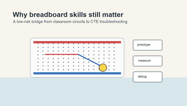
The breadboard matters too. If students cannot read the physical layout, their logic build problems may be wiring problems instead of thinking problems. That is why What Is a Solderless Breadboard? is a useful supporting article.
A beginner classroom routine for logic gates
- Show the gate symbol and name the rule.
- Write the truth table together.
- Predict what should happen for one input combination.
- Build or test that case in a low-voltage circuit.
- Compare the observed output to the truth table.
- Troubleshoot any mismatch.
This routine keeps the lesson grounded. Students see that the truth table is not separate from the circuit. It is the behavior the circuit should produce.
Common mistakes students make
- Memorizing gate names without understanding the rule.
- Forgetting that NOT has only one input.
- Mixing up AND and OR in the 1,0 and 0,1 cases.
- Thinking a bad breadboard connection means the truth table is wrong.
- Treating digital logic as unrelated to electronics or robotics.
Those errors are why this topic connects well with Circuits Students Should Understand Before Robotics. Logic gates are part of a larger control story, not a disconnected vocabulary list.
Where Mr Circuit fits naturally
The strongest product example for this topic is the Mr Circuit Lab 3 Digital Logic Gates STEM Kit because it matches the article's real-circuit approach. For teachers planning implementation, the For Schools and Educators page is the better planning destination.
Frequently Asked Questions
What is the easiest way to explain a logic gate?
Call it a simple rule-based circuit that checks its input conditions and gives one predictable output.
Why are AND, OR, and NOT taught first?
Because they introduce the main truth-table patterns students need before learning more complex gates.
Do students need coding to learn logic gates?
No. Students can understand logic gates through switches, LEDs, truth tables, and breadboard circuits before they write code.
Are logic gates part of electronics or computer science?
They are both. Logic gates are electronic circuits that also form the foundation of digital computing.
Why should students test truth tables with real circuits?
Because testing helps them see that symbols and tables describe actual circuit behavior.