A simple night-light circuit uses a light-sensitive resistor to change circuit behavior when the room gets darker. In a beginner breadboard build, the photoresistor helps control a transistor, the transistor switches the LED path, and a series resistor protects the LED from too much current.
Last updated: June 6, 2026.
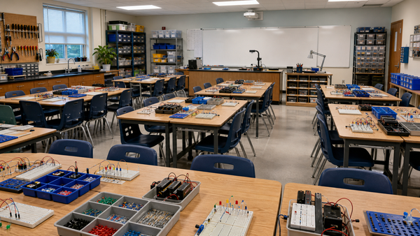
This kind of project works well in class because students can see both electronics and cause-and-effect at the same time. Cover the sensor and the output changes. Uncover it and the output changes again. That makes the lesson memorable, especially for students who need a visible reason to care about resistance, sensors, and switching.
What this circuit is meant to teach
Do not frame this as household wiring. This is a low-voltage educational build that helps students understand three beginner ideas:
- a sensor can change electrical behavior,
- a transistor can control an output path, and
- an LED still needs current limiting even in a sensor project.
The Mr Circuit Lab 1 Basic Electronics STEM Kit is the most relevant internal example because its product page explicitly includes a photocell, low-voltage power, and a night-light style project in the learning sequence.
What parts you need conceptually
| Part | Job in the circuit | Why it matters in class |
|---|---|---|
| Photoresistor or photocell | Changes resistance as light changes | Gives students a visible sensor input |
| Transistor | Acts as the switching element for the LED path | Introduces control without complex programming |
| LED | Shows the output state | Makes circuit behavior obvious |
| Series resistor | Limits LED current | Keeps the build safer and more predictable |
| Battery and breadboard | Provide low-voltage power and testing space | Support beginner-friendly assembly |
Adafruit's photocell guide explains the big idea simply: photocells do not all behave exactly the same, but they all change resistance based on light level. SparkFun's photoresistor lesson then adds the beginner electronics bridge: a light-sensitive resistor becomes useful when it is part of a circuit that turns that resistance change into a voltage or switching change.
How to explain the circuit before building it
Start with the behavior, not the wiring. Tell students: “In bright light, the sensor behaves one way. In darker light, it behaves another way. That change helps control whether the LED path is on or off.”
Then identify the roles:
- The photoresistor is the input.
- The transistor is the decision point or switch.
- The LED is the output.
That structure also makes a clean bridge to future robotics and sensor lessons.
Build order that works for beginners
- Build and test the LED output path first.
- Add the resistor that protects the LED.
- Place the transistor and explain that it will control the output path.
- Add the photoresistor side of the circuit.
- Test the circuit in brighter light and then by covering the sensor.
This order reduces confusion because students can verify the output before adding the sensor logic. If the LED path never worked in the first place, they cannot learn much from the sensor part of the lesson.
Why the photoresistor matters
The key classroom idea is that the sensor is not “making light” or “making power.” It is changing a circuit condition by changing its resistance. That is why the article What Is Resistance? is a useful internal follow-up if students need the concept unpacked more slowly.
SparkFun's guide to using a photoresistor in a beginner kit explains that a resistance-based sensor often needs to be part of a voltage-divider style arrangement so the circuit can respond to the change meaningfully. Students do not need every formula on day one, but they should understand that the sensor changes the balance of the circuit.
Why the LED still needs a resistor
A sensor project does not cancel LED safety. The LED still needs current limiting. If students skip that part, they learn the wrong lesson. The best internal refresher is Why LEDs Need Resistors, followed by How a Resistor Works in a Simple LED Circuit.
That is also why teacher pacing matters: first make the output path trustworthy, then add the sensor behavior on top of it.
What students should observe
| Condition | What to ask students | What they may observe |
|---|---|---|
| Room is bright | What is the sensor telling the circuit right now? | The LED may stay off or behave less strongly, depending on the design |
| Sensor is covered | What changed in the input? | The LED may turn on or become more active |
| Sensor is uncovered again | Did the output return to the earlier state? | The circuit should respond consistently if the wiring is correct |
Those observations are stronger than asking students to memorize that a photocell is “a resistor that changes.” The build gives them evidence.
Common troubleshooting points
1. The LED path was never tested by itself
If students add every part at once, they do not know which section caused the failure.
2. The LED resistor was skipped or misplaced
The output circuit has to be current-limited correctly to behave predictably.
3. The photoresistor is being explained like a switch
It is better to say that the sensor changes resistance with light, and that the rest of the circuit turns that change into an output decision.
4. The board layout is confusing students
If the class is new to breadboards, link back to what a solderless breadboard is once that article is live. Many project errors are layout errors, not concept errors.
How to turn this into a stronger STEM lesson
Ask students to predict first, then test, then revise their explanation. That sequence turns a novelty project into a real STEM routine. The For Schools and Educators page is the best internal destination for teachers thinking beyond a single activity, because it shows how reusable low-voltage builds fit a wider classroom system.
You can also ask students how the same sensor idea could be used in a robot, alarm, or automatic light. That keeps the project from ending at “it worked” and moves it toward “what could this control next?”
Frequently Asked Questions
What does a photoresistor do in a night-light circuit?
It changes resistance as the light level changes, which helps the circuit respond differently in bright and dark conditions.
Why is a transistor used in a simple night-light circuit?
The transistor acts like a control element or switch for the LED output path.
Does the LED still need a resistor in a sensor circuit?
Yes. The LED still needs current limiting so the circuit remains safer and more predictable.
Is this the same as wiring a household night-light?
No. This article is about a low-voltage educational circuit for classroom or beginner breadboard use.
What is the best first test after building?
Verify the LED path first, then cover and uncover the photoresistor to see whether the output changes as expected.