Skip to product information
You have found the best product for learning and teaching electronics technology to HVAC, AUTOMOTIVE, ROBOTICS, DRONES, HAM Radio and STEM classes.
Mr Circuit Lab#1301-LAB Teach Basic Digital Logic Gates which are the building blocks for all computers and controllers. - For STEM students & Future Robotics Engineers and Technicians
This lab is an introduction to Digital Logic Gates for all STEM Technology programs. All computers use logic gates and is it important for future engineers and technicians to understand them.
Skill Set for the Mr Circuit Lab 3 "Digital Logic Gates"
Congratulations!
You have found the best product for learning and teaching electronics technology to HVAC, AUTOMOTIVE, ROBOTICS, DRONES, HAM Radio and STEM classes.![]()
*** Because Mr Circuit Labs are reusable, you can offer real electronics technology training to your students for a very few dollars per student.
Mr Circuit Lab#1301-LAB Teach Basic Digital Logic Gates which are the building blocks for all computers and controllers. - For STEM students & Future Robotics Engineers and Technicians
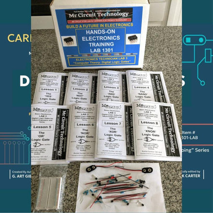
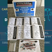
When you order this Mr Circuit DIGITAL LOGIC GATES Lab, #1301-LAB, you will receive a resealable white lab box, printed lessons and workbook, online video presentations of each experiment, all necessary experiment parts, and a Solderless Circuit Board.
This lab is an introduction to Digital Logic Gates for all STEM Technology programs. All computers use logic gates and is it important for future engineers and technicians to understand them.
There are only 8 total Digital Logic Gates. There are 4 basic Logic Gates and 4 inverses of these gates making a total of 8. The are YES, NOT, AND, NAND, OR, NOR, XOR and XNOR. These logic gates work with Binary Logic so their inputs and outputs only work with two states, i.e. TRUE or FALSE.
In electronics a TRUE is represented by a HI or a 1, and a FALSE is represented by a LO or a 0. Using electronics, these 8 digital logic gates can perform highly complex mathematical operations.
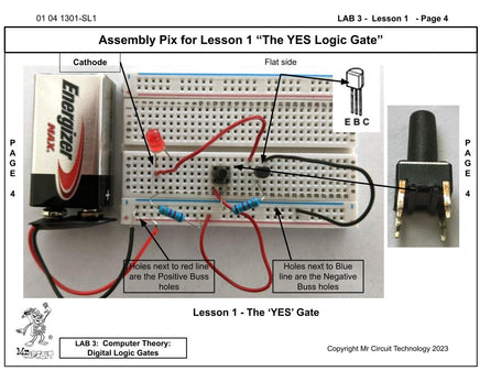
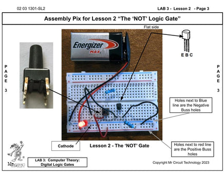
In this lab, you will learn what each logic gate does and how to use a Truth Table to describe its function. In addition, you will actually build electronic circuits that perform the function of each logic gate. You will use transistors, resistors, switches, jumper wires, and LEDs.
This lab will prepare you to learn Boolean Algebra and other techniques to design digital circuits.
Skill Set for the Mr Circuit Lab 3 "Digital Logic Gates"
-
Describe all eight of the Digital Logic Gates
-
Explain the Rules and draw the symbol for the ‘YES’ Digital Logic Gate
-
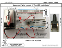
Build an electronic ‘YES’ from discrete components on a Solderless Circuit Board
-
Explain the Rules and draw the symbol for the ‘NOT’ Digital Logic Gate
-
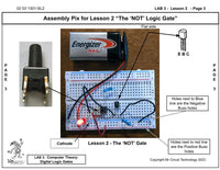
Build an electronic ‘NOT’ from discrete components on a Solderless Circuit Board
-
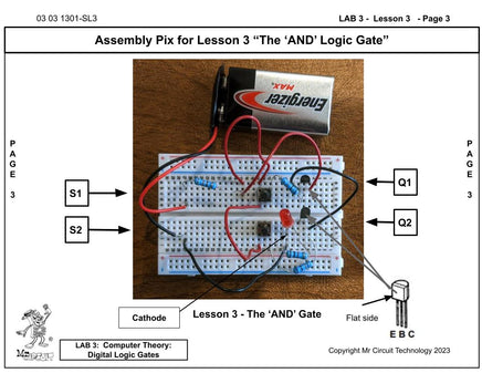
Explain the Rules and draw the symbol for the ‘AND’ Digital Logic Gate
-
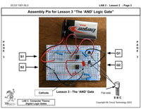
Build an electronic ‘AND’ from discrete components on a Solderless Circuit Board
-
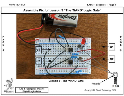
Explain the Rules and draw the symbol for the ‘NAND’ Digital Logic Gate
-
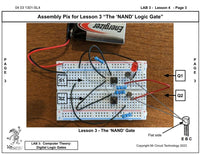
Build an electronic ‘NAND’ from discrete components on a Solderless Circuit Board
-
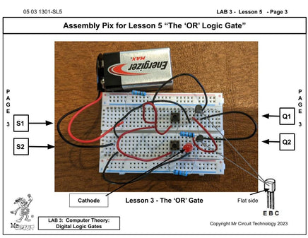
Explain the Rules and draw the symbol for the ‘OR’ Digital Logic Gate
-
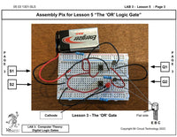
Build an electronic ‘OR’ from discrete components on a Solderless Circuit Board
-
Explain the Rules and draw the symbol for the ‘NOR’ Digital Logic Gate
-
Build an electronic ‘NOR’ from discrete components on a Solderless Circuit Board
-
Explain the Rules and draw the symbol for the ‘XOR’ Digital Logic Gate
-
Build an electronic ‘XOR’ from discrete components on a Solderless Circuit Board
-
Explain the Rules and draw the symbol for the ‘XNOR’ Digital Logic Gate
-
Build an electronic ‘XNOR’ from discrete components on a Solderless Circuit Board
Created, manufactured, and distributed by Mr Circuit Technology
We accept Credit / Debit Cards or Public School Purchase Orders.
Thank you from G. Art Gibson, author and educator
Mr Circuit Technology 805-295-1642
We ship orders the same business day we receive them. Thank You, Mr Circuit
Order Today! Your student will love it.
